


![]()


![[ Polski ]](../../images/POLA001.gif)
![[ Deutsch ]](../../images/GERM001.gif) What's new in the current Version of Software AnTherm
What's new in the current Version of Software AnTherm
Thermal bridge heat and vapour transfer simulation program AnTherm in its version 9 provides vast amount of functions and abilities which perfectly support the user in his daily work. Moved to the newest technology further improvements have been applied to the new version adding additional efficiencies when working with the software.
Continuous further development of the software up to its current version has been strongly influenced by users' feedback. Thanks to all subscribers for showing their trust to the project.
Since the project start in 2003, which followed the early works of 1980's and 90's, and the initial release of version 1 (deployed on 6th June 2005) further continuous improvements to the program have been achieved. In September 2007 the version 3 has followed the version 2 which has been made available in January 2007. After the version 4 has been deployed in November 2008 and the version 5 in March 2010. Technologically updated version 6 was made available in September 2010 which was followed by then Anniversary version 6.100 in June 2011. The version 6.106 continues implementation of major user wishes on the one hand, and additionally introduces the 4-D, time dependant, transient simulations for the year 2012. The version 6.114/5 optimizes the functionalities. The version 7.125 integrates the optimum of functionalities on top of the newest platforms.
Further intermediary versions are available to subscribers of the software maintenance (update-subscription) program.
Complete up-to-date Documentation, Manual, Short Reference and Tutorial make starting the work with this powerful application easy and straight forward.
New functionality in Version 9.136.2 (February 2019) compared to Version 9.136.2
Radiation Temperature:
- AnTherm now contains an interface with SolRad. Results can be imported from SolRad in order to compute Radiation Temperatures in AnTherm from the Global Radiations and the Air Temperatures. This interface is a separate tool for the stationary case, and for the instationary case it is included in the Periodic Data Editor of the HARMONIC/TRANSIENT option.
Custom Material Database:
- In addition to the Material Database there is now a Custom (User-Defined) Material Database. Every customer has the possibility to specify their own materials, save them and paste the data into the Element Editor.
New functionality in Version 9.136.1 (October 2018) compared to Version 9.136
Chi Value Calculator:
- AnTherm now contains a tool to calculate the point thermal transmission coefficient (Chi Value).
New functionality in Version 9.136 (February 2018) compared to Version 8.133
Project Window:
- AnTherm permits the combination of several model files to projects. Upon the user's wish a list of projects is displayed, the user is able to choose a project and then a model file associated with this project. In this way it is easier than previously to retrieve a particular model.
Inhomogenous Layer Calculator:
- For inhomogenous layers (such as bricks) homogenous replacement constructions can be computed and the equivalent values can be retrieved.
Three-Space Psi Calculator:
- The Psi value can now be calculated for a three-space case with an unheated buffer space.
New functionality in Version 8.133 (March 2017) compared to Version 8.132
DXF/IFC Import:
- It is now possible to import 3-dimensional DXF files. Moreover, models created with Autodesk Revit can be imported as IFC files.
New functionality in Version 8.132 (November 2016) compared to Version 8.131
DXF Import:
- The DXF Import now supports elements with slopes and roundings.
New functionality in Version 8.131 (March 2016) compared to Version 8
Surface Temperatures:
- AnTherm is able to display a graph showing the surface temperature gradient of a room.
Include several images:
- The user can now create several images in the Results 3D window and include them in the dynamic report.
New functionality in Version 8 (October 2015) compared to Version 7.126
Slopes and Roundings:
- AnTherm now supports the input of oblique and round elements as well as the rotation of elements by an arbitrary angle.
Probe Point:
- The selected probe point is visualized by a red cross in the Results 3D window.
New functionality in Version 7.126 (2014) compared to Version 6.114
Graphic related to the Psi-Value:
- The automatic evaluation of the Psi-Value also displays a graphical visualization.
New Baubook catalogue:
- The new format of the Baubook catalogue (formerly known as ÖBOX) is now supported. The data from the new Baubook catalogue can be imported into AnTherm.
Newest platform, Updated documentation, Comfort and Speed in Version 6.114 (November 2012) compared to V.6.106
Platform:
- The newest version runs within Windows 8 too!
Documentation:
- Intro 81_Dampfdiffusion.htm extended
- New: Introduction\82_Harmonic.htm, Introduction\83_Transient.htm, Introduction\86_Multicore.htm, Introduction\88_Stereo3D.htm.
Introduction\70_Auswertungen.htm split to 71_Visualisierung_GraphischeAuswertungen.htm and Merkblatt_instationaer.pdf/htm integrated (also due to THESIM) - Documentation of the VAPOUR-Option in the Tutorial. Use case with Isolinie, pressure difference explained...
- EcoTechBaustoffeForm has the documentation in English too
- The Tabs of Transforms link directly onto the respective help (earlier via Transform);
The Tabs of Materials/Surfaces link directly onto the respective help (earlier via Materials/Surfaces)
The Tabs of Results3D link directly onto the respective help (earlier via Results3D) - Localised DE/EN of Snap3D, FinrasterParams
Input, Data Entry:
- Cause DXF Import produces only material elements, we derive from the "Material name" the name for the boundary condition too (space, surface and power source name) - this is helpful for changing element type later appropriately.
- Within the context menu of the Materials List the menu "Replace Materials on All Elements" has been added (always visible). If duplicates occur, the first material in the row wins.
Within the Materials List, after importing materials "from another Project" we offer the option (dialog) "Replace Materials on All Elements" with those currently imported. - Within the context menu of the Surface List the menu "Replace Surfaces on All Elements" has been added (always visible). If duplicates occur, the first surface in the row wins.
Within the Surface List, after importing surfaces "from another Project" we offer the option (dialog) "Replace Surfaces on All Elements" with those currently imported. - Within the context menu of the Materials List the menus "Purge all Materials", "Apply Material", "Select Elements by Material" have been added.
- Within the context menu of the Surface List the menus "Purge all Surfaces", "Apply Surface", "Select Elements by Surface" have been added.
- Within the context menu of element editing, also Assign to "To Type" Material(s), Powers(s), Spaces(s), Empty(ies) have binn added. All currently selected elements receive the chosen type (confirmation required if multiple elements are selected).
- New messeges: AssignMaterial.NoneOfSelectedAreMaterialBox, AssignSurface.NoneOfSelectedAreSpaceBox, AssignRoomName.NoneOfSelectedAreSpaceBox, AssignPowerName.NoneOfSelectedArePowerBox
- JoinedTransform Undo/Redo Buttons added.
- MaterialsEditor and Surfaces, Undo/Redo Buttons added, rest of the buttons replaced with the new style.
- LayerBrowser Undo/Redo Buttons added.
- ProbePointsForm renamed to "Probe Points / Extremal (Min/Max) Locations" (in main menu "&Probe points / Min/Max")
ProbePointsForm received the context menu (New/Delete/GoTo/Pick from Project) and Tooltips on the point list, GoTo, Report.
ProbePointsForm return to the recently used tab (Settings.LastSelectedProbePointsFormTabPageName, the default is the "Min/Max-Tab"; After "Collect Point" switches automatically the the "User-Tab"). - ApplicationSettingsForm has Tabs, LastSelectedApplicationSettingsFormTabPageName.
ESC-key closes SettingsForm, ApplicationSettingsForm
Solver, die Calculation Engine:
- DeltaTraceItNo added IterationControlParameters, currently not editable.
- Adjusted the default for isorpars = "/O0 /o(1.20:-0.05) /d.0000001 /i300000 /I10"
- FineGridParams modified. New option - suppress in all axis directions.
- SolverParameters splitt into several tabs, most importatn first, old variant in "General"
- The setting AskToCalculateVaporIfCanCalculateButOff and AskToCalculateInstationaryIfCanCalculateButOff control the preference by the user (nee category "X Advanced Solver Settings"):
- The standard reponse to the query "if, when sufficient data for the VALOUR or TRANSIENT calculation exists but the calculation was not requested, that shell be turned on", has been replaced with NO!
- The EN ISO 13788 defines for the eq. (14) the factor ("water vapour diffusion conductance coefficient") by (2*10 hoch -10 kg/Pa*m*s). Turning that onto the units used in AnTherm we receive the factor 1,3888 (instead of 1,5 following earlier standards). To stay conformant with current standards the factor has been changed from 1,5 to 1,3888 - (specifically to 10/7,2).
Due to this modification you shall expect slight changes to the results VAPOUR calculation!
Harmonic / Transient Solver:
- The limit maximum number of harmonics is <PeriodLegth\2 (because the integral number ist currently used) and <1000 (Solver can go up to 2000). This is for ans arbitrary period lenght (i.e. the is only one common validation rule).
When HARMONIC is only performed this limits are tightened: Year:6; Day:6; Custom:6 - and this is enough to THESIM too.
The means that the number of periods can be editied, but the get/set of InstationarySolverParameters will check if valid.
The inserting of any additional arbitrary period lengths is provided only with the Transient option (as previously). - The setting "HARMONIC/TRANSIENT Option Active" has been split to two independent once.
TRANSIENT can be switched off in the case whrn no time dependant evaluations are planned (i.e. no entry of PeriodicBC, SharedTime, and no Timeline or Animate evaluations).
Turning off Harmonic "suppresses" Transient also.
Evaluation of Results:
- If BOTH fRsi criteria are fulfilled we display conformance message: "fRsi - Mould growth- and Condensation assessment criterion is fulfilled".
- ResultsReport now contains ProbePoints results. Due to this consolidation the ProbePointsReport has been made obsolete and has been purged!
- With the HARMONIC option alone only steady state evaluations will be offered (together with the dinamic, harmonic indicators)
- ClipBoardImageSizeLimit c_maxBitmapDim = 1 << 13 (i.e. 8192) and the will be a temporary bitmap crated to check this.
The default for the setting KeepViewAspectRatio = true (was false)
Comfort, Specialities:
- Materials out of the Ecotech-Materialdatabase will be appnded with the suffix "[ecotech.cc]"
- EcoTech Material Browser (Materials Database) has been integrated to AnTherm (the menu displayed within View->Data Entry and Tools; available only if some EcoTech product - e.g. EcoTech-GBR - is installed also).
- First and initial release "Lambda Equivalent Calculator (Lambda-EQ Tool)" deployed. Help only in DE. LeitwertLambdaEqParameters are saved with the project.
Divers:
- New License feature VERSION201211 starting from the Version 6.113,
- The license file can be dropped over the respective tab within ApplicationSettingsForm. Validation done immediately.
- U-Value Calculator redesigned (layout).
- Missing a 3D licence blocks 3D processing: Menus Disabled: File->New, File->Convert, File->Import, no saving of 3D/3DS
- The limit to Recently-Used raised to 200; first 35 receive a short cut.
and much more...
Transient, Dynamic, Time-Dependant, 4D in the version 6.106 (December 2011/January 2012) compared to V.6.100:
Visualization:
- Fixing the range of Color Bar to arbitrary domain is now possible (the range will not change with new data); fixing the domain of isolines too; and this for every active evaluation function independently – for optimal and comparable visualization of results.
- The function specific evaluation parameters will be retained (for active evaluation function: temperature, heat flux, pressure, ...):
- When switching the secondary function their respective “function specific” parameters will be automatically set, restored also (colour table+value interval, Isolines: start+step+bold+interval,, …)
- The function specific parameters do not run into the collection of "Results3D Parameter" (neither Project nor Standard). The function specific evaluation parameters are application setting.
- The selected active evaluation function (and vector) will be retained;
By that function specific evaluation parameters are kept too. - The “Clamp range” limits the isolines created to the values within the Min/Max interval specified.
- The position of SliceX/Y/Z (an by the of Probe too) will be kept as far as possible
- Probe-moveable is initially off (but pickable is on by default) to avoid confusion on 3D navigation
- Naming changes:
- Tab HedgeHog -> Vectors (HedgeHog)
Solver, the Engine:
- Relevant components of the solver were upgraded to use newest Operating System libraries.
- For the harmonic/periodic calculation the is “Custom period length” available in addition to “Day” and “Year” (requires HARMONIC option).
- Only one of the three available Periods (Day, Year or Custom) can be requested for the calculation (requires HARMONIC option).
- The volumetric heat capacity and the complex base solutions are now double to allow higher precision of evaluation (requires HARMONIC option).
Evaluation:
- The Coupling Coefficients Report out of solution of dynamic, harmonic problem with power sources will contain the Harmonic Distribution Factors for each harmonic (Power Source to Space) – as a complex number and respectively as the Amplitude und Phase Lag (requires HARMONIC option).
- Condensing humidity calculator now outputs Mould-Humidity (0.8 condensing humidity) and Corrosion-Humidity 0.6 condensing humidity).
4D, time dependant, transient evaluation:
- The option TRANSIENT was introduced - it provides methods for thermal analysis of dynamic behavior of building constructions when boundary conditions are changing in time periodically and the effects of heat capacity (heat storage) must be considered - in addition to the HARMONIC option/a>.
- Allows free entry of higher number of harmonics to Solver,
- specification of Periodic Boundary Conditions and
- executing Time-Based evaluations (Timeline, Results3D Animation).
- TThe Results, ProbePoints and Results3D are calculated for some chosen Time-Point (SharedTime) also set within boundary conditions/li>
- (and it "includes" HARMONIC by its nature!.
- For the main period of Year/Day/Custom can be defined how many harmonics shall be calculated (the harmonic periods are stored currently as integers, rounded):
- Year: max of 365 harmonics,
- Day: max of 24 harmonics,
- Custom: max of 1000 harmonics. (internally the solver can go up to 2000 harmonics).
- For the purpose of dynamic, transient problem (subject to the TRANSIENT option) the boundary conditions window mutates to allow input of time dependant quantities – preset with ConstantValue out of steady state problem.
- The PPeriodic / Harmonic Data Editor supports creation, editing and management of timelines for various periodic data types: RegularPoints, RegularMeans, IrregularMeans, IrregularSteps, ConstantValue, HarmonicCoefficients.
Graphical and Tabular input methods are provided. - Project file now stores Periodic Boundary Conditions (Spaces and Power Sources). For each Period (including MainPeriod=0 - steady state) a set of boundary conditions is retained as template (and available to be saved after boundary conditions are applied).
All BCs will be merged by their Names into the projects BC-Template upon apply. This will retain BCs even when spaces or power source are renamed or removed from the project.
Compatibility with the earlier versions is provided (TemplateBoundaryConditionValues will be read and moved to BoundaryConditionTemplates for the respective period). - For the evaluation the harmonic base solutions are combined with the respective harmonic coefficients of the boundary condition the belong to (complex linear combination). The resulting distribution harmonic coefficients it then passed for Fourier synthesis for specific evaluation time point T.
- The number of harmonics used during synthesis (#Hsynth) can be reduced.
Evaluating in with only 0-th harmonic or only Constant Boundary Conditions is identical to Steady State results - The Animate Time Dialog is used to define temporal animation of transient evaluation by automating changes to the evaluation time point T.
Animated Results 3D renderings can be optionally recorded to an AVI file. - Timelines window displays synthetic, temporal, time dependant results at selected Probe Points together with timelines of synthetic boundary conditions applied.
Comfort:
- The 3D Scene Export retains the export format recently used (comparable to image export).
At the end of a scene export a confirmation message (or an error description) is being shown - When repeating the image-export or 3D-scene-export the indexed file name will be automatically offered (Name_001, _002, …).
 Display of vertical tabs labeled with icon symbols instead of text labels provides a very compact display of them presumably in one column (controlled from a tab context menu and/or application settings). All tabs show their respective tooltip also (name, any further information).
 - For users with multiple license dongles and varying license files there is new setting „AlternativeLicenseFileNamesList“ allowing to point multiple license files with different capability variants (i.e. multiple HID files) coupled with different dongles.
The info dialogue displays the currently used path oft he license file too.
Performance, parallelization (subject to MULTICORE-option):
- The default of the application setting SolverRunOnMultipleProcessors = ON (was OFF, also when reported number of processors is less than 2). The user shall optimize the number of processors (SolverMaxNumberOfProcessors) used concurrently.
- Creating (calculation) of the superposition of base solutions for specific boundary conditions is optimized to executed in parallel on multiple CPUs.
- Creating (calculation) of secondary functions for Result3D is multithreaded distributed automatically multiple CPUs.
- The harmonic Fourier analysis (while interactively creating the time dependant profiles of periodic data for the climate) and the synthesis of the harmonic base solutions with respective boundary conditions are optimized for parallel execution on multiple CPUs (subject to TRANSIENT option).
Data Entry:
- Supplemented materials of EN ISO 10456
ON31-A, ON8110, ISO10077,ISO6946,TGL moved from the ecotech-souce to avoid duplicates - EcoTech Material Browser (Materials Database) included (available only with EcoTech installed).
- The new setting "AlphaSurfaceTransmittanceHidden" (default=true) hides the input of Alpha (=1/Rs) in Element Editor and Surface Editor.
The Modeling Report outputs Rs values only (except in a case of Alpha=0).
Various:
- The runtime environment of AnTherm has been fully migrated to the newest MS Framework .NET3.5/4.
This very extensive upgrade leads to much better runtime behavior of the application and provides next milestone towards further development. - The new installer (SETUP.EXE) will automatically download and install all required system components (is such additional components are required).
- HARMONIC license feature replaces the lexically “curious” INSTATIONARY entry (still meaning HARMONIC option) in the activation file.
- Some windows did not scale on some font-scaled Win7 systems
- Textual output of space-elements (and surfaces) compacted, Rs output first, Alpha follows (in braces)
Output of Material-elements has been compacted also (less white space). - Isosurface will now always include its normal vectors (unfortunately 100% slower on creation, but required for the scene export)
- The number of equation above which a warning message shall be shown can be set by the user (by default 1.000.000 equations is currently seen as excessive, even the solver can go for about 20.000.000 - on 32-bit system). The warning message can be disabled too.
- The new setting "MulticoreOptionActive" allows to temporarily turn off this option.
Extended application settings "InstationaryOptionActive", "Stereo3DViewOptionActive", "MulticoreOptionActive" are now ReadOnly (instead of being hidden) when the targeted license option is not available.
and much more...
Anniversary version 6.100 (June 2011) compared to V.6:
Input and Model Entry:
- Revolution: i.e. a 3D model can be constructed out of a 2D one by revolving the 2D object by 90° around vertical or horizontal rotation axis.
- The Materials Database has been extended to include data set of ArchiPHYSIK (APH9) and EcoTech (Builddesk AT)
Solver (the calculation engine):
- If solver calculation bails out due to parametric constrains an additional diagnostic message showing the solution status (state of basis solution, solved/aborted, availability of the coupling coefficients matrix) is displayed (e.g. when solver aborts after reaching the maximum number of iterations set).
The dialog shown also offers direct jump to solver documentation. - The coordinate data precision of the fine-grid has been doubled.
Past projects resulting in more precise fine grid will be recalculated automatically when needed.
Evaluation and Reports:
- Warning indicators (*) and a warning message are shown within the coupling coefficients report if the precision criterion concerning the magnitude of relative close-up errors of base solutions calculated is not satisfied.
- Warning indicators (*) or (**) and the respective warning message are shown along with the output of fRsi temperature factors within the results report when respective design temperature factors are undercut while assessing the risk of condensation or mould growth (if so requested by application settings of those design factors and warnings).
- The user can decide if fRsi temperature factors are displayed and assessed for two space cases only (when the two spaces are the only boundary conditions) or to warn if fRsi temperature factors are dependent on further conditions too.
- The output of the matrix of thermal coupling coefficients, power source distribution factors, coefficients of vapour diffusion coupling and harmonic conductances, when more then 7 (or 3) spaces are considered, is now structured into consecutive groups of 7 (or 3) rows (the report does not overflow to the right anymore).
Within the results report the g-weighting factors are output in consecutive groups of 5 columns respectively. - The window „Probe Points“ has been redesigned. Two separate tabs:
- Points entered or collected by the user (tab „User“)
- Automatically calculated locations of extreme values (tab „Min/Max“)
The button „Report“ displays the Probe Points Report (earlier „Apply“).
The button „Go To XYZ“ moves the slices X/Y/Z in Results3D window (same as the double click onto data record mark).
- The „Probe Points window“ lists locations for all extremes of all boundary conditions (spaces and power sources). The listing is updated upon update to boundary conditions. It can be used to easily „jump“ onto such extreme locations within Results3D window.
- The „probe points report“ now shows warmest surface points (max), in addition to coldest points (min), for each space too.
It displays extreme values (min and max) for all power sources also.
Extensions to 3D visualization and evaluation:
- Additionally to the evaluation of condensing humidity on component surfaces there are secondary functions of mould growth humidity (0.8*Cond.H) and corrosion humidity (0.6*Cond.H) calculated also.
- The evaluation of surface condensing humidity (Condens. RH, Mould RH, Corrosion RH) is no more offered on adiabatic surface (will be calculated and evaluated on space surfaces only).
- Control panels will show tooltips if conflicting settings are in force:
- If there is no vector field available for evaluation the tabs of Streamlines and Hedgehog will show tooltip.
- If the Surface is set to opaque, solid display the tables of Streamlines, SliceXYZ, Isosurface etc. will show a tooltip stating, that objects rendering evaluation within the interior of the model are obscured by the surface display.
- Orientation Marker added to the display. The location and the size of the marker display can be changed – controlled with the panel „3D“.
- Panning the display with the keyboard is now available for interaction (Shift+Cursor keys and Shift+Numeric Block keys).
Pan-Buttons have been added to the panel „3D“. - Streamlines are created at much higher precision. The integration step of earlier projects will be automatically adjusted (new default value 0.1mm, values below 0.051mm will be raised by 10, values smaller then 0.005mm set to 0.05mm)
- Streamlines rendering longer then 100.000 segments and tubes collectively rendering in more than 1.6 million vertices (depending on the number of tube sides set within application settings) will be rendered as lines only. This shall avoid running out of memory when very complex streamlines were rendered as tubes.
- Flying to an isometry (shift-double-click within Isometries window) acts on Results-3D window only (animation is off within Elements3D now).
- The display of streamline(s) is now independent of the “active” setting of slice planes X/Y/Z.
- PointPicker moves the probe point X/Y/Z location when the surface, isosurface or slice plane are clicked (double clicked) (“Pickable” setting of the “Probe” panel in Results3D-Window).
- ProbeCross has been extended with a PointWidget allowing to drag and move the X/Y/Z probe point with the mouse (“Moveable” setting of the “Probe” panel in Results3D-Window).
3D stereo view extensions:
- New stereo modes added:
- Checkerboard
- Left- and Right Eye
- Images rendered by passive stereo modes (i.e. now all modes except Crystal Eyes) can be exported as an image now too.
- The Anaglyph Stereo Mode can be set to render compatible with further filter types of glasses (OpenGL-setting StereoAnaglyphColorMask).
- New export modes for 3D Scene: X3D, X3D-Binary, POV-Ray
Documentation:
- The „Theoretical Background“ has been extended by adding further generic essays.
Comfort improvements and further fixes:
- Dropping (drag & drop) a project file over the main application window will open that file.
Dropping of a Waebru component file is also supported as a shortcut for quick import. - Import of Heat3 v.4 Files added.
- The Element Browser columns Number/Type display coloured by element’s colour.
- Power sources are still shown in red but now by using a transparent brush (the colour of elements overlapped by the power source shines through the brush net).
- The selection of multiple elements in Elements2D window is emphasized with alternating white/black strokes (instead of white only line which was insufficiently visible).
- Clipping planes of the camera are updated correctly even for 2D and 1D objects.
- Layout fixes in “Register Underlay Image” for systems with scaled fonts.
- Surface Edges are now colorized according to the evaluation scalar function chosen.
- The default value of "OverwriteProjectWithoutAsking"=True (earlier False). The application will not repeatedly ask to name the project for already saved project data when results are requested.
- New application setting “Help Window shown TopMost”: Help window will be shown topmost to application windows and automatically minimize with the application (this is the windows default behavior). When turned off (the default) the help window can be set behind the application window via typical desktop window manager.
- Axes displayed on Elements3D are now shown at „Outer Edges“ (earlier „Closest Triad“).
- On systems which virtualize OS folders (eg. Vista) the activation shall always proceed via the „Alternative License File AnTherm.HID“. The license file shall be placed into folder not controlled by the virtualization (e.g. user folder).
- Saving 3D images is now possible even on very weak graphic systems with WindowsXP (e.g. Netbook with Intel Graphics).
- Elements copied via the clipboard retain their overlapping order (the order is not derived from the selection order anymore).
- Result fields of evaluations related to boundary conditions not connected to the heat transport network (model) are rendered blank within reports.
- On systems older then Windows Vista (ie. Windows XP) the default setting "EnableVisualStyles = FALSE". This is required to compensate for implementation errors of the operating system (text of vertical tabs in Results3D window do not show).
- New Application setting OpenGLSetting: ExplicitBackfaceProperty: will assign BackfaceProperty=FrontFace for modelSliceX, modelSliceY, modelSliceZ, model, sliceZ, sliceY, sliceX, isosurface, surface; Used to resolve rendering issues on (very few) systems rendering only one side of surfaces. (Workaround added to Documentation FAQ too)
- Resolved compatibility issue raised on older Windows XP machines during image export of 3D renderings
and many more...
Technology, tooling and efficiency - the new version 6 (September 2010):
 New technology and platform, new techniques, new perspective:
- Full technology migration to the new, proven MS .NET Windows platform: still simpler install, faster execution, shorter calculation times, automated runtime optimization of the program adjusting to technical equipment of the computer. The startup and shutdown of the application are fulgurous too.
- Using the latest visualization platform in its newest version: still more exact, partly acquired patented algorithms, fully in double precision, new demand driven and efficient visualization pipelines.
- Even cases numerically poorly conditioned can be calculated precisely and quickly without any user intervention (very detailed structures, slopes and curvatures modeled with detailed stepping, thin foils, holders, spikes etc.) - relaxation factor can now freely go up to the maximum of 2.0 without the risk of instability and eventual abort without reaching the solution (earlier 1.998).
- New installation procedure (setup.exe) downloads and installs prerequisite Click-Once components (MS.NET 3.5 Runtime, Crystal Reports Basic Runtime for Visual Studio 2008).
1000 reasons to Undo/Redo - the whole works:
- Undo/Redo function allows comfortable rollback to previous editing state - up to 1000 steps can be undone.
- The undone sequence can be redone also, thus mistaken editing can be easily avoided or fixed.
- The window responsible for the action will be exposed automatically (on undo and redo) providing the ability to exactly observe the action sequence executed.
- Undo is mostly usable in following windows: Elements2D, Elements23, Element Browser, Element Editor, 3D-Layers, Materials and Surfaces.
- Shortcuts: Ctrl-Z / Ctrl-Y
Improved automation of the Psi-Value (Ψ) determination:
- The Ψ-Value determination has been reworked and redesigned to allow automated Psi-Value determination in further 2D cases by far.
- Additionally the tool will automatically choose most logical U-Value profiles identified automatically - connections like "interior-interior" will be offered when other options are absent.
- Layered constructs of the Psi-Value calculation can be edited, changed, saved or even independently loaded within the U-Value calculator.
- If required one can manually override numbers used for calculation which where initially automatically determined.
- In such cases for which no automated calculation support can be offered by the tool the message will be displayed - the manual calculation is still possible based on values provided in Coupling Coefficients and Modeling reports.
 Comfort and convenient simplification of data input:
- Further/multiple application instances can be launched directly out of the program (menu Tools).
This allows simultaneous editing of several projects or project branches if needed. - Shortcut keys and context menus are made consistently available throughout all editing windows.
- Selection, duplication and reordering buttons have been placed on editing windows.
- Editing windows used for translation, rotation, mirroring and stretching have been put together into common transformation window.
- The dialog Stretch offers additional button >-Shrink-< opposite to the stretch function.
- Snapping grid and snap settings are available in relevant editing windows.
- Snap behavior while dragging (moving) elements has been changed - the thickness of the element will stay unchanged in any case.
- The element selection menu of the context menu of element editing offers only options actually really available in the given context.
- Additonal period lengths for the harmonic calculation (in addition to year and day) can be entered within advanced solver settings (Solver Parameter Dialog).
Refined and additional output:
- Vapor diffusion coupling coefficients: Coupling coefficients from the vapor diffusion calculation are output kg/Pa*h also.
- Indicator of the precision criteria (close-up error by default: 10e-5) displayed in coupling coefficients report.
If the criteria is missed stars (*) or (**) are displayed along with precision information. (see also EN ISO 10211 A.2-e) - The output order of harmonic coupling coefficients goes from longest to the shortest period length now.
- Emphasized isolines (Bold) are now displayed as continuous pipes (without breaks).
- Level of detail of tubes (streamlines, emphasized isolines), arrows and cone (Hedgehog) renderings can be set within application settings. The default number of tube sides has been reduced from 12 to 4.
- New high quality styles of glyph vector field visualization (Hedgehog): arrow-smooth, cone-smooth.
- Binocular visualizations with Red/Cyan glasses (anaglyph) in addition to earlier implemented stereo 3D renderings.
Further changes and improvements:
- Control elements and windows are displayed with (new) visual styles (can be changed via application settings).
- Status display in solver window synchronously resembles the computation progress.
- Settings controlling the outline rendering moved to separate control panel (better clarity of the general panel)
- Naming of arrow-, color table- and stereo 3D-styles have been localized conformant to user interface language chosen.
- Application settings can be now also reached out of the tools menu.
- Vertical tabs of control panels within Results 3D window now display graphical icons for convenience (can be turned off via application settings).
- The default value of the advanced application setting "Allow multiple application instances" switched to TRUE (earlier FALSE).
- Overflow exception on GDI+ while displaying at very high zoom levels are handled properly now.
- Renewal of the license module: It now reports locked adapters to the about window (by suffix). USB license dongles are also reported.
- The switch to turn off the display of Tip-Of-The-Day is kept inactive until all tips has been seen 2 times and the each had 10 seconds to display in average or the user went 10 times through all the tips (clicked through).
- Changes made in fine grid- and solver parameters dialogs are ignored if dialog is aborted.
- Default number of iterations for transient calculation changed to 300.000 (earlier abort after 100.000 iteration steps).
- New license feature VERSION201009 required for execution of the version 6.89 and higher.
- Thermal surface resistance values for window, frame and door calculations as required by EN ISO 10077 (also reduced Rsi values for corners) included in standard surfaces (appropriate to calculate thermal resistance of respective components).
- Examples of transient harmonic calculations as provided within EN ISO 13786 are included with the installation.
- Optimizations to the storage of AnTherm projects reduce the size of already small AnTherm project files slightly (ca. -15%)
- The application documentation (help) updated for the new version.
and much more...
Transient, fast and immersive - the version 5 (March 2010):
The capability matrix of the program functions has been significantly extended with additional options. In front of all the transient, harmonic, periodic extension together with high performance multiprocessor capability and frontier visualization technology complete the next major milestone in continuous development of the application.
New functional results:
- Fully automatic calculation of the transient, harmonic thermal coupling coefficients (with HARMONIC-Option).
The Coupling Coefficients Report displays matrices of harmonic thermal coupling (one matrix for each chosen period given as complex number and as matrix of value and argument ). That output allows easy readout of Lpe (coupling coefficient exterior to interior) or time lag (phase lag, shift) values. Diagonal elements are significant (contrary to steady state case) and can be used for calculating effective heat capacities.
Same as with steady state case there is no need to know nor to apply any boundary conditions to obtain these results! - New Secondary function „Relative Core Humidity %“ (with VAPOUR-Option)
- Within the Boundary Conditions window can be decided if secondary functions for the Results3D-Evaluation shall be calculated.
Performance, speed, quality:
- The default setting of Solver precision lowered to 10-9 (earlier 10-6 to 10-11).
- The application setting "Run solver on multiple processors“ controls the subdivision of complex computation onto many (or all available) processors or processor cores installed (with MULTICORE-Option).
- Time needed to create the results report has been reduced nearly to nop (< 1 second!!! earlier sometimes >1 minute).
- Te calculation of the field of condensing surface humidity runs faster by a factor of 8 to 10.
- Much better interactive experience due to significant reduction of redundant renderings while interacting with control panels of the Results3D window.
- Memory management of the 3D visualization has been improved. Memory demands of Elements3D window reduced without performance impact.
Benchmarks and conformity with standards:
- Updated validation benchmark report for EN ISO 10211:2007 and EN ISO 10077:2003 can be viewed online. All benchmark data (AnTherm project files) is included with the installation (Help->Example Load…).
- Operations on systems with non Western European character sets.
- Operations on Windows 7 (32bit and 64bit).
 New and faster, more efficient 3D evaluations and visualizations:
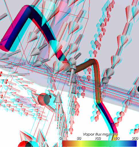
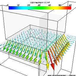
- HedgeHog (Vector Arrows) visualization of heat- or vapor stream vector field added. The vector field can be shown with arrows, cones or lines of fixed length or scaled by vector norm, at points on uniform, regular mesh. .
- The display of the Probe-Cross can now be controlled independently from Slice Planes .
- Adjusted default setting for streamlines allow visualizations with more detail at higher precision - also in the case of components connected with ground.
- Additional color table RGB_INV added.
- Recent setup of the visualization settings (Result3D Parameter) can be restored automatically on initial display of the Result3D Window (new application setting „Restore Result3D Params“).
- Recent setup of the camera position (the isometrics) can be restored automatically on initial display of the Result3D Window (new application setting „Restore Camera Position“).
- Binocular 3D stereo view (addition hardware my be required) available (with STEREO3DVIEW-Option).
More flexibility during data entry and model input:
- Input of Rho (ρ mass density) und Ce (c heat capacity) available (with HARMONIC-Option)
- automatic update of material color on change of lambda value (the default behavior) can be turned off.
- The context menu of element editing function extended with many new operations (stretch, assign to ... new group, etc).
- Stretching (thickening) of elements allows easy adjustment of insulation thicknesses.
- Swapping coordinate pairs (X1<->X2, Y1<->Y2, etc.) within Element Editor and while "Duplicating“ has been automated.
- The Building Physics Database http://WWW.BPHDB.COM (Kurt Battisti) can be included within Materials Database.
- The listing of standardized surface properties updated conformant to ISO 6946 and 13788.
- A 3D project can be converted to 3D layered type.
- Lately unused corners of Elements 2D windows (also Elements23 window) now contain buttons used to „Fit“, „Zoom In“, Zoom Out“ and „Image-Export“.
Improved data import and import functions:
- Import of Image underlay/overlay: For 3D projects there are up to three image underlay slots available - to the planes XY, YZ und ZX. The image will be displayed within the Elements2D window (either as underlay or transparent overlay).
- DXF-Importer shall now read all common text file line endings: Windows (CR LF) - Macintosh (CR) - Unix (LF)
- Within the DXF-Import Dialog one can set the number of decimal places at which coordinate values imported shall be rounded. DXF coordinates are now read in in double precision.
Furthermore:
- U-Value Calculator display R-Value too (above the U-Value).
- The documentation (manual, reference, etc) has been fully updated and extended as it has been done always at each release (done also for any intermediary release deployment).
- and more...
Culmination of improvements in the version 4 (November 2008):
The License Model has been extended with update-subscription program (software maintainance) providing instant access to newest developments during the subscription period to all subscribers. Furthermore, time limited one year licenses allow better budgeting of license fees simultaneously connected to the newest available version at each entrance to the next year subscription.
- Fully automatic calculation of the linear thermal transmittance correction term Psi for two dimensional two-space cases (Psi-Value Determination).
- Output of characteristic U-Values at adiabatic cut-off planes for two- and three dimensional heat bridges.
- Characteristic indicators (coupling coefficients, points of critical temperatures, fRsi etc.) can be evaluated even for equations of many millions of cells (i.e. tens of millions of nodes) - thanks to better memory management implementation (remark: graphical evaluations can be switched off).
- In calculations of models with power sources it is sufficient to supply one space (temperature) for successful simulation.
- Projects can be saved within very deep directory structures or even onto network drives.
- Processing of layered 3D projects is better supported with the new layer editor. Layered 3D models can be mirrored along Z-direction also.
- Reordering functions of elements have been improved and extended (for better support of overlapping)
- Graphical selection and editing functions have been improved (Lasso, Sizer)
- 2D images (e.g. all 2D windows) can be saved or transferred via the clipboard (in addition to 3D views)
- The material database can be extended with a download of modest ÖBOX materials
- Material- and surface properties can be easily picked from other projects; The projects materials and surfaces lists can be sorted.
- The calculation is reinitiated after any changes to solver parameters (e.g. precision settings)
- The grid (equation) generator at material boundaries processes material changes (e.g. lambda ratio) at higher precision. The calculation will restart automatically if required.
- The precision of the solver has been improved by the significant order of magnitude. Close-Up errors of less then 10-10 can be reached without any additional computational time. Same applies to temperature deviation (termination condition). Solution result of earlier calculations will be transformed to higher precision automatically.
- The performance of the solver has been further improved (especially within the equation generator). Status view onto the solver process is not delayed anymore.
- The calculation process (the solver) can be aborted at any time
- The term „adiabatic cutoff planes“ introduced consequently instead of "wonder foils"
- Higher precision of super fine grid of temperatures within areas of power sources.
- Streamlines at corners of the boundary or adiabatic planes will not be missed.
- Responsiveness and the level of interactivity of the 3D result view has been further improved even for extremely complex visualizations.
The quality of colorful images has been increased even further. - The position of the colorbar can be arbitrarily changed.
- The number of decimal digits for labels on isolines (t.g. isotherms) and colobar can be set arbitrarily
- The mobility of licenses has be extended with the "hardware dongle option" (adjustment to the license model).
- The English version of the program is supported with complete documentation in English.
- The VAPOUR-option (if licensed) can be turned off temporarily.
- The new tool "Simulation Folder Cleaner" supports quick removal (deletion) of simulation results created during earlier runs and not needed anymore
- An alternative location of the license file can be set within extended application settings. The path can contain any valid URI (ie. http://server/path/AnTherm.HID).
Essential improvements in the September 2007 version 3:
- DXF (Acad) Import has been reengineered to gain significant performance gain (factor of 10.000 !). This allows efficient and easy integration of very detailed CAD models into AnTherm. Such very complex models come into existence if, within CAD program, orthogonalization of modeled slopes and curvatures has been performed (this is required for AnTherm import).
- Repaints of element list for very large and complex projects has been sped up significantly (now about 10 times faster). This allows efficient processing of models of even many thousand elements without disturbing latencies.
- Speed of bulk operations (e.g. material assignment to many selected elements) has also been improved significantly. This allows efficient processing of models of even many thousand elements without disturbing latencies.
- Context menus of element editing show names of spaces/rooms, power sources, groups, materials and surfaces in alphabetically sorted lists (according to the current language setting). This provides much easier element selection on these criteria.
- f*Rsi is calculated by normalized definition f*Rsi = (T*si - Te)/(Ti - Te) (instead of 1-g0) – delivering same result for two-space-case for which, and only for which, it shall be used (for three- and more space cases g-values must be reported according to normalization - g-values are reported without any change compared to earlier program versions).
- Mouse wheel can be used to Zoom or Roll within the 3D-evaluation (now consistent with graphical 2D input)
- Zooming with the mouse wheel (within graphical input and evaluation) can be executed more precisely (the sensitivity of wheel movement have been lowered and configured more precisely).
- The license file is being stamped with asymmetrical signature barring any transport errors.
- Installation and execution within Microsoft Windows™ Vista has been ensured.
Mature functions published in earlier version 2:
 Streamlines in equidistant intervals of heat stream (or vapor stream) from the space edge in 2D case. This evaluation is possible for 2D projects or other project types in which the modeled construction is fully homogenous in the Z-direction an no space connections exist in this direction.
Speedup and stabilization of Streamline evaluations. The „kernel“ of streamline evaluation has been reengineered significantly resulting in much better quality of results an high stability. Much energy has been brought into finding a compromise between speed, memory requirements and quality.
The integration step factor now relates to minimum step size of the Runge-Kutta method. Actual step size is controlled and adapted automatically – from one fine grid cell to the next. This provides very detailed and precise presentation of streamlines for heat stream fields and vapor diffusion streams too!
User interface of project specific material- and surface lists has been reworked and improved. IBO BTK2006 materials (preliminary content) have been included into material database.
Accessing material properties (the material list) from element editor has been simplified and made much more intuitive.
Pressing F1-key shows context dependant help and information for currently active window.
Conductance matrix (coupling coefficients, Leitwertmatrix) can be exported to CSV file.
Within translate window the duplication can be initiated simultaneously. This is the main starting point for entering of more complex constructions, especially when modeling sloped ones.
 Element choice list is shown in tabular form containing type- and coordinate columns (past versions where shown unstructured).
Execution performance of element list has been significantly improved for showing very large lists and supporting massive bulk selections. This allows modeling and processing of constructions built of many thousands of elements.
Captions on axes and labels on isolines can be adjusted easily.
Selected isolines can be emphasized (as Tubes) (Bold each N).
3D visualizations can be controlled by 3D-keyboard navigation in addition to mouse control.
An Airspace calculator can be started from "Tools" menu - calculates equivalent heat transfer coefficient for small cavities. Many functions of this airspace calculator have been deeply integrated into the program (automatic takeover of extents, transfer of resulting value onto selected elements, etc.)
A U-value calculator has been loosely integrated.
Actually power density (entry of boundary condition) of a power source is used for evaluation. Provisioning of power density in W/m³ can be easily derived from manufacturer's data.
Result reports for power sources display the power, power density and the volume (result report, probe points report).
In addition to absolute coordinate entry for elements (X1 to X2, Y1 to Y2, Z1 to Z2) relative thickness (dX, dY, dZ) can be entered.
Within surface editor and element editor characteristics of the surface (element type "Space") can be provided as Alpha (surface transfer coefficient) or alternatively as Rs (transfer resistance).
 Clipboard can be used to copy/cut/paste one or more selected elements. Clipboard can be used between projects or even separate program instances.
Drag-Drop of materials from the material list onto elelemts is supported now.
Prior to calculation start various validations are executed and, if data available is insufficient to start the computation error messages are shown - in addition or instead of those shown in solver window (e.g. (none or not enough space attachments, 0- or 1-dimensional construction, empty construction, etc.)
Further secondary functions (within Results3D) added: saturation vapor pressure distribution within the construction (hPa).
Features of the extended option „vapor diffusion“ have been integrated (partial pressure field, pressure difference field, vapor diffusion stream vector field).
Annotations of isolinies can be placed dense (proximity and step size shall be as small as 1mm from now on).
The radius of the tube emphasizing selected isolines (Bold each-Nth) can be set to less then 1mm (even 0) too. Both adjustments together allow visualization of strongly magnified construction areas.
Interested?
Contact
us for more information.
Or try and evaluate the demonstrational version just now!